Note: This blog post explains the fundamental switching concepts and basic configurations. Before diving into switching concepts, it’s important to have a solid understanding of some fundamental networking concepts including : Network Devices, Network Topologies, IP Addressing and Subnetting, OSI Model, and Cisco Switch Initial Configuration. These foundational concepts provide a solid framework for understanding the principles and technologies involved in networking and subsequently, switching.
Switching is the process of forwarding data frames from one network device to another. It occurs within a local network, and is responsible for creating paths for data to flow efficiently between devices. Switches are the key devices that perform this function. In switches, there are different types of ports that serve specific purposes and provide various functionalities :
- Access Ports : Access ports are used to connect end-user devices (such as computers, printers, or IP phones) to the switch. They belong to a specific VLAN. The frames sent and received through access ports are not tagged (untagged) with VLAN IDs. This means that the devices connected to an access port are usually not aware of the VLAN configuration. When a frame leaves a device connected to an access port, the switch automatically adds the appropriate VLAN tag to the frame based on the VLAN configuration of the access port. This tagging happens internally within the switch, and the frame is sent with the appropriate VLAN tag through the switch.
- Trunk Ports : Trunk ports are used to interconnect switches and carry traffic for multiple VLANs simultaneously. They configured to support 802.1Q VLAN tagging, which means that frames leaving a trunk port are tagged with the appropriate VLAN ID.
- EtherChannel (Link Aggregation) Ports : Etherchannel, also known as link aggregation, allows multiple physical links between switches to be combined into a single logical link for increased bandwidth and redundancy. Etherchannel aggregates the bandwidth of the individual links to create a high-bandwidth channel between switches.
- Management Port : Some managed switches have a dedicated management port, which is used for remote management and configuration of the switch. The management port is used to access the switch’s management interface, usually through a web interface or command-line interface (CLI).
- Uplink Ports : Uplink ports refer to the ports on a switch that are used to connect to higher-level network device, such as routers or other core switches. The purpose of the uplink port is to facilitate communication between different segments or layers of the network hierarchy. Regarding the physical characteristics of an uplink port, it can be any type of Ethernet port, including Fast Ethernet (100 Mbps), Gigabit Ethernet (1 Gbps), 10 Gigabit Ethernet (10 Gbps), and even higher speeds Ethernet port.
- Stack Ports : Stack ports are used in switches that support stacking, a technology that allow multiple physical switches to operate as a single logical switch. Stack ports are used to create a high-speed backplane connection between the stacked switches, allowing them to function as one unit and share resources.
- Console Port : The console port is a serial port used for direct local management and configuration of the switch. It provides a direct connection to the switch’s operating system through a terminal emulator.
How Does Data Flow in Switches?
1. Encapsulation at the Device Level (Source Device)
When a device (for example, computer) connected to a switch wants to send data to another device on the same network, it encapsulates data into a Layer 2 frame.
- The data starts at the Application Layer and is passed down the OSI model (from Layer 7 to Layer 2).
- At the Data Link Layer (Layer 2), the device encapsulates the data into a frame. This frame includes:
- Source MAC address (the MAC address of the sending device).
- Destination MAC address (the MAC address of the intended receiving device).
- The payload (data).
- Trailer (for Frame Check Sequence (FCS)).
2. Frame Reception by the Switch
The source device then sends the frame to the switch over the access port to be forwarded.
- Since it’s an access port, the frame is untagged, and no VLAN information is present in the frame at this point.
3. De-Encapsulation and Learning by the Switch
When the switch receives a frame, it examines the source MAC address of the frame. The switch checks its MAC address table to see if the source MAC address is already recorded. If the source MAC address is not in the table, the switch updates it MAC address table with the source MAC address and the incoming port on which the frame was received. This is how a switch learns about MAC addresses (MAC address table learning). This process helps the switch maintain a record of which devices are connected to which ports. The MAC address table is dynamic and can change over time as devices connect or disconnect. If the same MAC address is seen on a different port, the table is updated to reflect the new port location. Before forwarding the frame, the switch performs a lookup in its MAC address table to determine the appropriate outgoing port for the destination MAC address.
4. Frame Forwarding
- If the destination MAC address is already in the table, the switch knows the device’s corresponding port and forwards the frame only to that port.
-
If the destination MAC address is not found in the MAC address table, the switch forwards the frame to all ports except the incoming port (flooding). This is known as “unknown unicast flooding”. After flooding the frame to all ports (except the incoming port), the switch relies on the receiving devices on those ports to process the frame :
1) Correct Destination Device :
- The correct destination device will recognize its own MAC address in the frame’s destination MAC address field.
- It will accept the frame and extract the encapsulated data from the frame.
- The destination device processes the received data, which could involve displaying it on a screen, storing it in memory, or taking other appropriate actions.
2) Incorrect Destination Device :
- The incorrect destination devices will ignore or drop the frame since the destination MAC address doesn’t match their own MAC address.
The switch also follows different procedures based on the frame type :
- Unicast : If the frame is unicast (sent to a specific device or one-to-one communication), the switch performs a lookup in its MAC address table to determine the appropriate outgoing port for the destination MAC address.
- Broadcast : If the frame is a broadcast frame (sent to all devices on the network or one-to-all communication), the switch broadcasts the frame out of all its ports. This ensures that all devices connected to the switch receive the broadcast data.
- Multicast : If the frame is a multicast frame (sent to a specific group of devices or one-to-many communication), the switch uses special multicast MAC addresses to forward the frame only to members of that multicast group.
Virtual LANs (VLANs)
VLANs (Virtual Local Area Networks) are a technology used to logically segment a single physical switch into multiple virtual switches, without requiring separate physical infrastructure. A VLAN is a logical partition of a Layer 2 (data link layer) network. This allows us to isolate traffic, improve security, and manage the network more efficiently. VLANs allow network administrators to divide a large, flat network into smaller, isolated segments. Devices within the same VLAN can communicate with each other as if they were connected to the same physical switch, even if they are physically connected to different switches. Devices in one VLAN cannot directly communicate with devices in other VLANs, providing a level of isolation that helps prevent unauthorized access. For example, a device within VLAN 10 cannot directly communicate with devices within VLAN 20. By dividing a network into multiple VLANs, broadcast domains are also segmented. Broadcast traffic is limited to devices within the same VLAN, reducing unnecessary broadcast traffic on the entire network. To identify which VLAN a frame belongs to, VLAN tagging is used. When a frame leaves a device in a VLAN, it is “tagged” with a VLAN identifier (VLAN ID). This tagging happens internally within the switch, and the frame is sent with the appropriate VLAN tag through the switch. In VLANs, tagging is the process of adding a special tag or identifier to Ethernet frames to indicate which VLAN the frame belongs to. This process allows devices to communicate based on VLAN membership, regardless of their physical location.
- Default VLAN : Most switches come with a default VLAN (usually VLAN 1) that includes all ports when they are not explicitly assigned to other VLANs. It’s a best practice to avoid using VLAN 1 for user traffic due to security reasons and potential vulnerabilities associated with the default VLAN.
- Data VLAN : Data VLANs are created to carry user traffic, such as data from computers, servers, or other devices in a network. Data VLANs separate user traffic from other types of traffic, such as management traffic.
- Voice VLAN : Voice VLANs are designed to support Voice over IP (VoIP) traffic from IP phones. These VLANs prioritize voice traffic to ensure high-quality voice communication and separate it from regular data traffic (user and management data traffic).
- Management VLAN : The management VLAN is used for network management purposes, such as accessing and configuring switches remotely. Devices used for network management, such as SNMP (Simple Network Management Protocol) servers, are typically placed in the management VLAN.
- Native VLAN : On a trunk link, one VLAN is designated as the “native VLAN”. Frames belonging to the native VLAN are sent without a VLAN tag over the trunk.
Basic VLAN Configurations
1) Creating a VLAN :
- VLANs are identified by a VLAN ID - a number between 1 to 1005 (Normal Range) and 1006 to 4096 (Extended Range)
Switch(config)# vlan <vlan-id>
2) Name a VLAN :
Switch(config-vlan)# name <vlan's name>
3) Assigning a port to a VLAN :
- By default, all the interface ports belong to VLAN 1 (Default VLAN).
- By default, the Administrative Mode of the port is dynamic auto, so the best practice is to change it to become a static port, an access port (access mode).
Switch(config)# int FastEthernet 0/1
Switch(config-if)# switchport mode access
Switch(config-if)# switchport access vlan <vlan-id>
4) Remove a VLAN port assignment or change a VLAN port membership :
- After completing this command, the interface port will automatically belong to VLAN 1 (Default VLAN).
Switch(config)# int FastEthernet 0/1
Switch(config-if)# no switchport access vlan
5) Deleting a VLAN :
Switch(config)# no vlan <vlan-id>
6) Display information about the switchport of the interface port :
Switch# show int switchport
OR
- Show the information only for the specific interface port.
Switch# show int FastEthernet 0/1 switchport
7) Display VLAN database :
Switch(config)# show vlan
OR
Switch(config)# show vlan brief
Trunk
In networking, a “trunk” refers to a high-speed connection between network devices, typically switches, that carry traffic for multiple VLANs simultaneously. A VLAN Trunk is a point-to-point link that carries more than one VLAN traffic. Trunks allow for the transportation of data between switches while maintaining the separation and identification of individual VLANs. Trunks are essential for extending VLANs across multiple switches and enabling efficient communication in large networks. Trunks use a technique called “VLAN tagging” to differentiate frames belonging to different VLANs as they traverse the trunk link. The most common standard for VLAN tagging on trunks is 802.1Q, defined by the IEEE (Institute of Electrical and Electronics Engineers).
802.1Q adds a 32-bit VLAN tag to the Ethernet frame’s header, enabling the identification of the VLAN to which the frame belongs. The VLAN tag includes a 12-bit VLAN ID (VLAN number), which allows for up to 4096 unique VLANs in a network. Frames that are sent to an access port (non-trunk port) are “untagged” because they are meant for devices within a specific VLAN and do not require a VLAN tag. Configuring IEEE 802.1Q trunk links :
1) Force the interface port to become a static port, trunk port (trunk mode) :
Switch(config)# int FastEthernet 0/1
Switch(config-if)# switchport mode trunk
2) Specify a native VLAN for untagged frames :
Switch(config-if)# switchport trunk native vlan <vlan-id>
3) If necessary, specify the list of VLANs to be allowed on the trunk link :
Switch(config-if)# switchport trunk allowed vlan <vlan-id-list>
4) Display information about the switchport interface :
Switch# show interface <interface-id> switchport
DTP (Dynamic Trunking Protocol) & Configurations
DTP is a Cisco proprietary protocol that runs on Cisco switches and is used to negotiate and automatically form trunk links between switches. DTP might not be suitable for multivendor environments. The primary purpose of DTP is to automate the process of trunk negotiation, making it easier for network administrators to configure trunk links without explicitly specifying whether a link should be a trunk or an access port. DTP is enabled by default on most Cisco switches. When we connect two switches or a switch to another device (such as a router), the ports will attempt to negotiate whether they should form a trunk link using DTP. DTP packets are exchanged between switches to determine if they can form a trunk link. If both switches agree, they form a trunk link and begin tagging VLANs across that link. DTP supports two modes (one mode per port), and there are conditions for a link to become a trunk link :
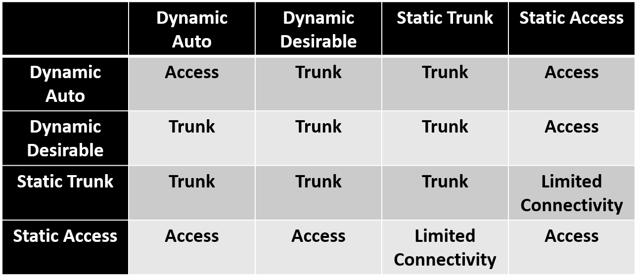
- Dynamic Auto : In this mode, the switch will respond to DTP negotiation requests, but it won’t actively initiate the negotiation. The port will only become a trunk port if the other end (switch port) initiates the negotiation and is configured as “Dynamic Desirable”. Otherwise, it will become an access port. This is the default mode of DTP.
- Dynamic Desirable : In this mode, the switch will both respond to DTP negotiation requests and actively initiate negotiation if the other end (switch port) supports it. If the other end is in “Dynamic Auto”, the port will become a trunk.
Refer to the table below :
1) Dynamic auto :
Switch(config)# int FastEthernet 0/1
Switch(config-if)# switchport mode dynamic auto
2) Dynamic desirable :
Switch(config-if)# switchport mode dynamic desirable
3) Disables DTP :
Switch(config-if)# switchport nonegotiate
4) Display information about the switchport interface, including DTP configuration :
Switch# show interface <interface-id> switchport
It’s important to be aware of DTP’s default behavior to avoid unintended trunk formation between switches. To explicitly control whether a port should be a trunk or an access port, we can manually configure the port as a trunk (using “switchport mode trunk”) or as an access port (using “switchport mode access”). This will override DTP’s default behavior for that specific port.
VTP (VLAN Trunking Protocol) & Configurations
VTP is another Cisco proprietary protocol that is used to manage and synchronize VLAN information across multiple switches within a VLAN management domain. VTP might not be suitable for multivendor environments. The primary purpose of VTP is to simplify the administration of VLANs in large networks. Instead of manually configuring VLANs on each switch, VTP allows the network administrators to create, modify, and delete VLANs on one VTP server switch, and these changes are automatically propagated to other switches in the same VTP domain. VTP messages are exchanged between switches to share VLAN information. VTP supports three modes for switches in a VTP domain (one mode per switch) :
- Server : A VTP server is responsible for managing VLAN information. VLAN changes made on a VTP server are propagated to other switches in the VTP domain.
- Client : A VTP client listens to VTP advertisements from VTP servers and applies VLAN changes received from them. However, a VTP client cannot make changes to VLANs.
- Transparent : A VTP transparent switch does not participate in VTP advertisements or synchronization but can still create and modify VLANs locally.
Basic VTP configuration :
1) Set the name of the VTP administrative domain :
- Example of domain name : CCNA, CISCO, CompanyA
Switch(config)# vtp domain <domain-name>
2) Configure VTP device mode :
Switch(config)# vtp mode <server/client/transparent>
3) Set the password for the VTP administrative domain :
Switch(config)# vtp paassword <password>
4) Display information about VTP configuration :
Switch# show vtp status
5) Display the current VTP administrative domain password :
Switch# show vtp password
It’s important to be aware that VTP has some potential drawbacks and risks, including VLAN overwrite and misconfiguration. VLAN information may accidentally overwritten or misconfigured when a new switch with a higher VTP revision number is introduced to the network. The revision number is used to keep track of changes to the VLAN configuration and to ensure that switches in the same VTP domain have the most up-to-date VLAN information. Whenever a change is made to the VLAN configuration on a VTP server switch, including deleting all or a specific VLAN, the revision number is incremented by one. Some network administrators prefer not to use VTP and instead opt for more manual and controlled VLAN management approaches.
Management VLAN
The main goal of a Management VLAN is to separate management traffic from regular user data traffic. Separating management traffic from regular user traffic ensures that network administrators can securely access and manage network devices without interference from general user data. It is dedicated solely to handling traffic such as Telnet, SSH, SNMP (Simple Network Management Protocol), Syslog, and other protocols used for monitoring, configuring, and troubleshooting network devices.
In-Band Management
In-band management refers to managing network devices over the same data network used for regular user traffic. In this approach, management traffic shares the same network infrastructure (routers, switches, and links) as user data traffic. Administrators access the management interface of devices using the same network path and IP addressing used for general user data.
Out-of-Band Management
Out-of-band management involves managing network through a separate dedicated network path that is independent of the primary data network. It provides a secure dedicated alternate access method into an IT network infrastructure to administer connected devices and IT assets without using the corporate LAN (in corporate environment). Network administrators access devices’ management interface using separate network connections and IP addressing specifically designated for out-of-band management.
EtherChannel (Link Aggregation)
EtherChannel, also known as link aggregation or port channeling, is a networking technology that allows multiple physical Ethernet links to be combined into a single logical link, providing increased bandwidth, redundancy, and load balancing. It provides redundancy by allowing traffic to continue flowing even if one or more individual links in the EtherChannel fail. EtherChannel is configured on participating switches or devices by grouping individual physical links into a logical bundle called an EtherChannel group. EtherChannel has certain implementation restrictions, including the following :
- Interface types cannot be mixed. For example, FastEthernet and GigabitEthernet cannot be mixed within a single EtherChannel.
- All member links in an EtherChannel must have the same speed and duplex settings.
- Different Cisco switch models have varying limits on the maximum number of interfaces that can be part of an EtherChannel group. Ensure that configurations are within the supported limits.
- All member interfaces within an EtherChannel group should be assigned to the same set of VLANs. Mismatched VLAN configurations can lead to traffic disruption or isolation.
- Consistent configuration. The individual EtherChannel group member port configuration must be consistent on both devices (for example, Switch 1 and Switch 2). If the physical ports of one side are configured as trunks (on Switch 1), the physical ports of the other side must also be configured as trunks (on Switch 2) within the same native VLAN.
- All ports in each EtherChannel link must be configured as Layer 2 ports (switchports).
- Each EtherChannel has a logical port channel interface. A configuration applied to the port channel interface affects all physical interfaces that are assigned to that interface.
There are two main configuration modes: Static (or unconditional EtherChannel) and Dynamic. In static mode, administrators manually select the links to be part of the EtherChannel group and configure them as such. Static mode configuration :
1) Enter the interface configuration mode :
- The “range” keyword allows us to select several interfaces and configure them all together.
- This example uses the interfaces FastEthernet 0/1 and FastEthernet 0/2.
Switch(config)# interface range FastEthernet 0/1 - 2
2) Create a port channel interface :
- The channel group number is in the range of 1 - 6 in the Cisco Catalyst 2960 switch because this switch only supports up to six EtherChannels.
- The “mode on” keywords identify this as a static EtherChannel.
Switch(config-if-range)# channel-group <channel-group-number> mode on
3) Enter port channel interface configuration mode and configure the port channel as a trunk interface :
Switch(config)# interface port-channel <channel-group-number>
Switch(config-if)# switchport mode trunk
4) (Additional configuration) We can specify the allowed VLANs :
- This example allowed traffic from VLAN 1, 2, 10, and 20.
Switch(config-if)# switchport trunk allowed vlan 1,2,10,20
In dynamic mode, protocols such as LACP (Link Aggregation Control Protocol) or PAgP (Port Aggregation Protocol) negotiate the formation and characteristics of the EtherChannel. These protocols allow ports with similar characteristics to form a channel through dynamic negotiation with adjoining switches.
PAgP (Port Aggregation Protocol)
PAgP is a Cisco proprietary protocol that aids in the automatic creation of EtherChannel links. When an EtherChannel link is configured using PAgP, PAgP packets are sent between EtherChannel-capable ports to negotiate the formation of a channel. When PAgP identifies matched Ethernet links, it groups the links into an EtherChannel. The EtherChannel is then added to the spanning tree as a single port. PAgP packets are sent every 30 seconds. PAgP checks for configuration consistency and manages link additions and failures between two switches. It ensures that when an EtherChannel is created, all ports have the same type of configuration. The modes for PAgP as follows :
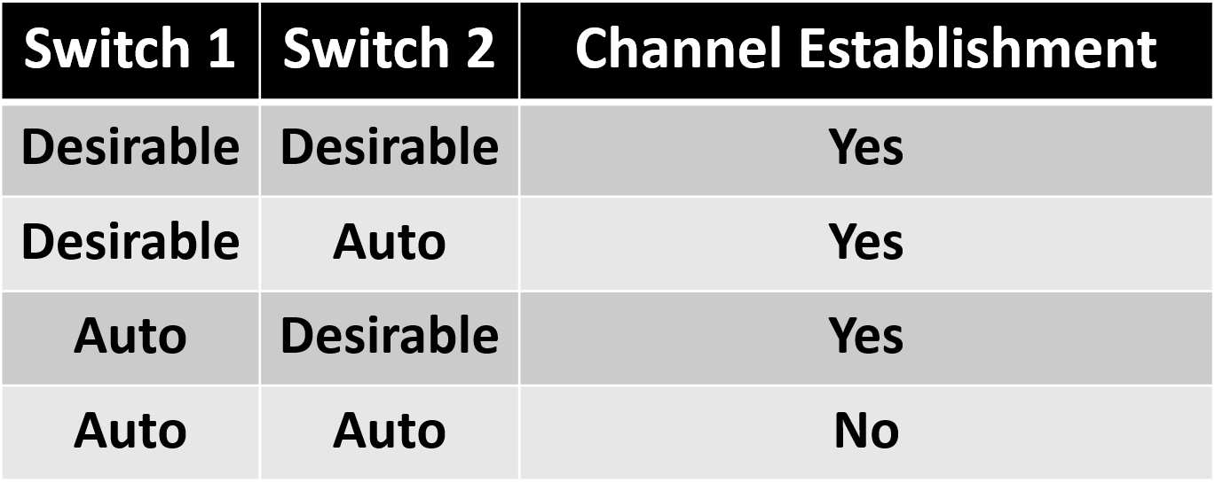
- Desirable : This mode places an interface in an active negotiating state, in which the interface initiates negotiations with other interfaces by sending PAgP packets.
- Auto : This mode places an interface in a passive negotiating state, in which the interface responds to the PAgP packets that it receives but does not initiate PAgP negotiation. Refer to the table below :
The configuration of PAgP EtherChannel is similar to that static EtherChannel :
1) Enter the interface configuration mode :
Switch(config)# interface range FastEthernet 0/1 - 2
2) Create a port channel interface :
- The “mode desirable” or “mode auto” keywords identify this as an PAgP EtherChannel configuration.
Switch(config-if-range)# channel-group <channel-group-number> mode <desirable/auto>
3) Enter port channel interface configuration mode and configure the port channel as a trunk interface :
Switch(config)# interface port-channel <channel-group-number>
Switch(config-if)# switchport mode trunk
4) (Additional configuration) We can specify the allowed VLANs :
Switch(config-if)# switchport trunk allowed vlan 1,2,10,20
LACP (Link Aggregation Control Protocol)
LACP is part of an IEEE specification (802.3ad) that allows EtherChannel. LACP allows a switch to negotiate an automatic bundle by sending LACP packets to the other switch. Because LACP is an IEEE standard, it can be used to facilitate EtherChannels in multivendor environments. LACP provides the same negotiation benefits as PAgP. LACP helps create the EtherChannel link by detecting the configuration of each side and making sure that they are compatible so that the EtherChannel link can be enabled when needed. The modes for LACP :
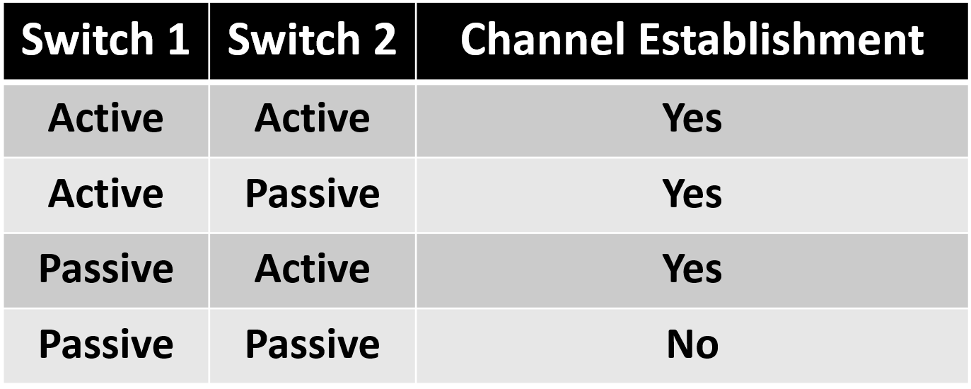
- Active : This mode places a port in an active negotiating state. In this state, the port initiates negotiations with other ports by sending LACP packets.
- Passive : This mode places a port in a passive negotiating state. In this state, the port responds to the LACP packets that it receives but does not initiate LACP packet negotiation. Refer to the table below :
The configuration of LACP EtherChannel is similar to that PAgP and static EtherChannel :
1) Enter the interface configuration mode :
Switch(config)# interface range FastEthernet 0/1 - 2
2) Create a port channel interface :
- The “mode active” or “mode passive” keywords identify this as an LACP EtherChannel configuration.
Switch(config-if-range)# channel-group <channel-group-number> mode <active/passive>
3) Enter port channel interface configuration mode and configure the port channel as a trunk interface :
Switch(config)# interface port-channel <channel-group-number>
Switch(config-if)# switchport mode trunk
4) (Additional configuration) We can specify the allowed VLANs :
Switch(config-if)# switchport trunk allowed vlan 1,2,10,20
Verify EtherChannel
As always, when we configure devices in a network, we must verify the configuration. If there are problems, we will also need to be able to troubleshoot and fix them.
1) Display the EtherChannel summary information :
Switch# show etherchannel summary
2) Display the general status of the port channel interface :
Switch# show interface port-channel
3) Display information about a specific port channel interface :
Switch# show etherchannel port-channel
4) Display information about the role of a physical member interface of the EtherChannel :
Switch# show intereface etherchannel
References
- VLANs (Complete Chapter) - Cisco Docs
- YouTube - VLANs
- Configuring VLAN Trunks - Cisco Docs
- VLANs and Trunking - Cisco Articles
- Cisco Networking Academy’s Introduction to VLANs (Refer to the Contents - Complete chapter of VLANs)
- Chapter 2: Scaling VLANs - Cisco NetAcad Powerpoint Presentation Slide
- Chapter 6: VLANs - Cisco NetAcad Powerpoint Presentation Slide
- Udemy - The Complete Networking Fundamentals Course
- Dynamic Trunking Protocol
- YouTube - CCNA Dynamic Trunking Protocol (DTP) Quiz
- Understand VLAN Trunk Protocol (VTP) - Cisco Docs
- Out-of-Band Management: What is it and why do I need it?
- EtherChannels - Cisco Docs
- Configuring EtherChannels - Cisco Docs
- Port Aggregation Protocol
- Link aggregation
- Link Aggregation Control Protocol - Cisco Docs
- Configuring Link Aggregation Control Protocol - Cisco Docs
- ETHERCHANNEL: LACP, PAgP, AND STATIC PROTOCOLS
- Etherchannel on Cisco IOS Catalyst Switch
- Chapter 4: EtherChannel and HSRP - Cisco NetAcad Powerpoint Presentation Slide