Note: Fundamental Routing Concepts - Routing (Concepts, Protocols and Configurations) and EIGRP (Enhanced Interior Gateway Routing Protocol)
OSPF, which stands for Open Shortest Path First, is a dynamic routing protocol and classified as a link-state routing protocol. This means that OSPF routers maintain detailed and up-to-date information about the state of network links and use this information to calculate the best routes. OSPF is an open standard and industry standard routing protocol, which means that OSPF can be used in any router from different vendors (multivendors). OSPF resides at layer 3 in the OSI model. OSPF exhibits all the characteristics typically associated with link-state routing protocols.
OSPF has evolved over the years, resulting in several versions. These versions include OSPFv1, OSPFv2, and OSPFv3. OSPFv1 was the initial version of OSPF and was designed for the IPv4 network. OSPFv1 was primarily used in early implementations of OSPF. OSPFv2 is the most widely deployed version of OSPF and the standard for IPv4-based routing. It includes various improvements and enhancements over OSPFv1. OSPFv3 is an adaptation of OSPF to support IPv6 routing and was developed to address the transition to IPv6.
In this blog post, OSPFv2 will be referred to as OSPF.
OSPF Packet Types
OSPF uses various types of packets to exchange information and maintain its routing process. These packets are integral to the operation of OSPF, and each serves a specific purpose in the OSPF protocol.
- Hello Packets : Hello packets are used to establish and maintain neighbor relationships between OSPF routers within the same network segment or area. Hello packets contain essential information, including the router’s Router ID (RID), network mask, and priority. Hello packets play a role in the election of the DR (Designated Router) and BDR (Backup Designated Router) on multi-access network segments. Reside in : “Init” and “Two-Way” states.
- Link-State Advertisement (LSA) Packets : LSA packets are used to exchange information about the network’s state and topology among OSPF routers. They help routers build and update their Link-State Databases (LSDBs). LSA packets contain detailed information about router interfaces, network links, and their states. Different types of LSAs are used for various purposes, such as Router LSAs, Network LSAs, Summary LSAs, and AS-External LSAs. LSAs are generated and exchanged throughout the OSPF neighbor formation and LSDB synchronization process.
- Database Description (DBD) Packets : DBD packets are used during the OSPF neighbor establishment process to exchange summary information about the LSAs each router has in its LSDB. DBD packets contain headers and brief descriptions of the LSAs in the sender’s LSDB. These summaries help routers determine which specific LSAs need to be requested and exchanged. Reside in : “Exstart” and “Exchange” states.
- LSA Request Packets : LSA request packets are sent by OSPF routers when they detect a discrepancy in their LSDBs and need specific LSAs from a neighboring router to update their databases. LSA request packets include information about the missing or outdated LSAs that the sending router requires. Reside in : “Loading” state.
- LSA Acknowledgement Packets : LSA acknowledgement packets are sent by OSPF routers to confirm the receipt of LSAs from a neighboring router. LSA acknowledgement packets are exchanged in various OSPF operational states where LSAs are sent and received.
OSPF Databases
OSPF uses three key databases to manage and store routing information within a router. These databases play a central role in OSPF’s link-state routing process.
- Neighbor Database or Adjacency Table : The Neighbor Database, also known as the Neighbor Table or Adjacency Table, maintains information about neighboring routers with which the local router has established OSPF neighbor relationships. This database contains details about neighboring routers, including their routers ID (RIDs), IP addresses, and the network interfaces through which they are reachable. The Neighbor Database is used to keep track of OSPF neighbors and their status.
- Link-State Database (LSDB) or Topology Table : The LSDB is the most critical OSPF database. It stores all the link-state advertisements (LSAs) received from neighboring routers. LSAs describe the state and characteristics of router interfaces, network links, and other information about the network’s topology. The LSDB is used by OSPF routers to perform SPF (Shortest Path First) calculations.
- Router LSAs : Describe the state of the originating router and its interfaces. OSPF LSA Type 1.
- Network LSAs : Represent multi-access networks and identifies the Designated Router (DR) and Backup Designated Router (BDR). OSPF LSA Type 2
- Summary LSAs : Summarize routes from one area to another within the OSPF domain. OSPF LSA Type 3 & 4.
- AS-External LSAs : Describe routes to networks outside the OSPF domain. OSPF LSA Type 5.
- Link LSAs : Provide detailed information about individual links on a router’s interfaces.
- Forwarding Database or Routing Table : The Forwarding Database or Routing Table contains the best routes to reach network destinations within the OSPF domain. It is derived from the information in the Link-State Database (LSDB) through SPF calculations. This database includes entries that specify the destination network, the next-hop router or interface, and the associated cost.
OSPF Operational States
In OSPF, the operational state refers to the current state or condition of the OSPF routing protocol on a router. OSPF routers go through several operational states during the process of forming and maintaining neighbor relationships, exchanging routing information, and ensuring the proper functioning of OSPF within a network. Monitoring the operational state of OSPF routers is essential for network administrators to troubleshoot issues and maintain network stability.
1) Down State :
- Description : When the OSPF process is not running or has been explicitly disabled on a router, it is said to be in the “Down” state. In this state, the router is not participating in OSPF routing and does not form OSPF neighbor relationships.
- Common Scenarios : The Down state can occur when OSPF is initially configured but has not been started, or when it has been intentionally disabled on a router.
2) Init State :
- Description : In the Init state, the OSPF process has been started, but the router has not yet sent Hello packets or established any OSPF neighbor relationships. It is in the process of initializing OSPF.
- Common Scenarios : The Init state occurs when the router is first configured with OSPF and the OSPF process is activated.
3) Two-Way State :
- Description : Once a router in the Init state sends Hello packets and receives compatible Hello packets from a neighboring router, it enters the Two-Way state. In this state, the router has detected a potential OSPF neighbor, but the neighbor relationship has not yet been fully established.
- Common Scenarios : The Two-Way state indicates that OSPF routers have detected each other on a network segment but have not yet exchanged enough information to form a complete neighbor relationship.
4) Exstart State :
- Description : In the Exstart state, OSPF routers exchange information about their initial sequence numbers, and the router with the higher sequence number becomes the master. This is an essential step in establishing a reliable OSPF neighbor relationship.
- Common Scenarios : The Exstart state is part of the OSPF neighbor formation process and is critical for synchronization.
6) Loading State :
- Description : In the Loading state, OSPF routers request and exchange specific LSAs to update their LSDBs. This step ensures that both routers have complete and up-to-date LSDBs.
- Common Scenarios : The Loading state is crucial for achieving LSDB synchronization and making accurate routing decisions.
7) Full State :
- Description : Once OSPF routers have successfully exchanged LSAs and verified that their LSDBs are synchronized, they enter the Full state. In this state, OSPF neighbor relationships are fully established, and OSPF routing information is being exchanged.
- Common Scenarios : The Full state is the desired operational state in OSPF, indicating that routers are actively participating in OSPF routing and exchanging routing information.
8) Dropped State :
- Description : If there are issues with OSPF neighbor relationships or if routers detect inconsistencies in the exchanged LSAs, they may enter Dropped state. In this state, OSPF routers will not forward traffic or exchange routing information until the issues are resolved.
- Common Scenarios : The Dropped state can occur due to various issues, such as misconfiguration, network problems, or authentication failures.
How It Works? OSPF Operation
We are using two routers, Router-A and Router-B, as an example.
1) Initialization
Router-A and Router-B are both configured with OSPF, but they start in the “Down” state, where OSPF is not running. To initiate OSPF, both Router-A and Router-B are configured to activate the OSPF process. Once OSPF is enabled, they enter the “Init” state.
2) Neighbor Discovery
In the “Init” state, Router-A and Router-B begin sending Hello packets on their respective interfaces. Router-A’s Hello packets reach Router-B, and Router-B’s Hello packets reach Router-B on a shared network segment. Upon receiving compatible Hello packets, Router-A and Router-B transition to the “Two-Way” state, recognizing each other as potential OSPF neighbors.
3) Exchanging Initial Sequence Numbers
In the “Two-Way” state, Router-A and Router-B proceed to exchange information about their initial sequence numbers. The router with the higher sequence number becomes the master. Let’s assume Router-A has the higher sequence number and becomes the master.
4) Exchange State
Router-A (the master) and Router-B exchange summary information about their LSAs in the “Exchange” state. During this process, they determine which specific LSAs need to be requested and exchanged.
5) Loading State
Router-A and Router-B enters the “Loading” state, where they request and exchange specific LSAs to update their LSDBs. They ensure that both routers have complete and up-to-date LSDBs. If there are any missing or outdated LSAs, they request them from each other.
6) Full State (Neighbor Relationship Established)
Once Router-A and Router-B have successfully exchanged LSAs and verified that their LSDBs are synchronized, they enter the “Full” state. In the “Full” state, OSPF neighbor relationships are fully established between Router-A and Router-B. Once OSPF routers successfully complete the LSDB synchronization process and enter the “Full” state, this is when the best path calculation takes place.
7) Exchanging and Updating LSDB
Router-A and Router-B continuously exchange LSAs as network topology changes occur. For example, if a new router is added or a link goes down, the affected routers generate new LSAs and share them with their OSPF neighbors. These exchanged LSAs are used to update each router’s LSDB. The routers compare the received LSAs with their LSDBs to determine if updates are needed. If Router-A receives an LSA from Router-B indicating a change in the network, it updates its LSDB accordingly. Both routers now have consistent information about the network’s topology, allowing them to make accurate routing decisions.
OSPF Cost Metric
OSPF uses a metric known as Cost or OSPF Cost to determine the best path to a destination network. The cost is used in the SPF (Shortest Path First) algorithm to calculate the most efficient path through the network (or the shortest path to a destination).
- OSPF Cost Metric : The OSPF Cost is a numerical value assigned to each link or network segment within the OSPF domain. The cost represents the “expense” or “effort” required to traverse a particular link or network segment. Lower values indicate a more desirable path, as it suggest a lower cost or shorter distance.
- Calculation of OSPF Cost : The OSPF Cost typically calculated based on the bandwidth of the link. The OSPF Cost is an integer value and must be a whole number. If something less than an integer is calculated, OSPF rounds up to the nearest integer. The formula to calculate the cost :
Cost = Reference Bandwidth / Link Bandwidth. Where :- Reference Bandwidth : Predefined constant value in OSPF (usually 100 Mbps or 100,000,000 bps)
- Link Bandwidth : Bandwidth of the link in bits per second (bps)
For example, if the link has a bandwidth of 1 Gbps, the cost would be :
Cost = 100,000,000 / 1,000,000,000
Cost = 0.1
Cost = 1 (rounds up to the nearest integer)
- Best Path Calculation : OSPF routers use the SPF algorithm to calculate the best path to a destination network based on the costs associated with the links in their LSDB. The SPF algorithm seeks the path with the lowest cumulative cost to reach the destination. When multiple paths have the same lowest cost, OSPF supports Equal-Cost Multipath (ECMP) routing, which means that traffic can be load-balanced (distributed equally) across these paths.
- Modifying OSPF Cost : Network administrators can influence OSPF routing decisions by modifying the OSPF Cost on specific interfaces or links. Increasing the cost on a link effectively makes it less desirable, potentially diverting traffic to other paths. Decreasing the cost makes a link more attractive for routing.
- Default OSPF Cost Values : OSPF defines default costs for common link speed. For example, a 1 Gbps Ethernet link typically has a cost of 1, a 100 Mbps Ethernet link has a cost of 10, and 10 Mbps Ethernet link has a cost of 100. These default values can be overridden by manually configuring cost values on specific interfaces.
OSPF Router ID
An OSPF router ID is a 32-bit value, represented as an IPv4 address. It is uniquely identify an OSPF router, and all OSPF packets include the router ID of the originating router. Every router requires a router ID to participate in an OSPF domain. The router ID is used by an OSPF-enabled router to :
- Participate in the synchronization of OSPF databases : During the Exchange State, the router with the highest router ID will send their database description (DBD) packets first.
- Participate in the election of the Designated Router (DR) : In a multiaccess LAN environment, the router with the highest router ID is elected the DR. The routing device with the second highest router ID is elected the backup designated router (BDR).
Cisco routers derive the router ID based on the following criteria :
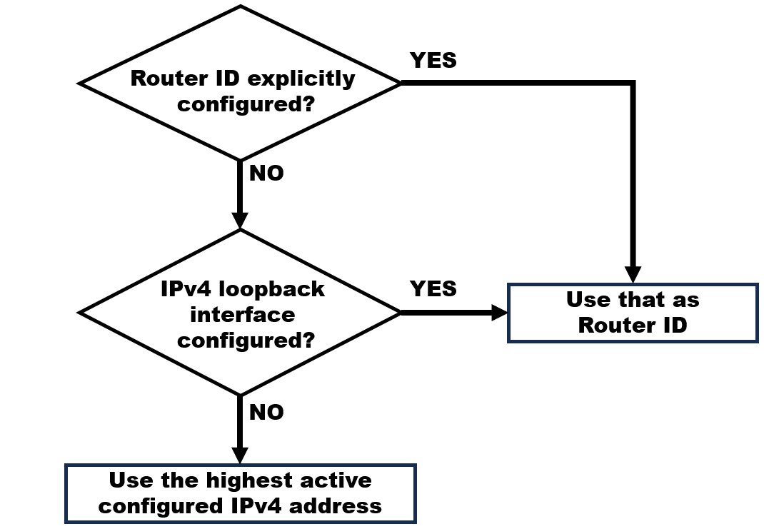
1) The router ID is explicitly configured using the router-id command. This is the recommended method to assign a router ID.
2) The router chooses the highest of any of the configured loopback interfaces. Loopback interfaces are virtual interfaces that are always up and operational, regardless of the status of physical interfaces. Instead of relying on physical interface, the router ID can be assigned to a loopback interface. Typically, the IPv4 address for this type of loopback interface should be configured using a 32-bit subnet mask 255.255.255.255. This effectively creates a host router. A 32-bit host router would not be advertised as a router to other OSPF routers. OSPF does not need to be enabled on an interface for that interface to be chosen as the router ID. Cisco routers prioritize loopback interfaces over physical interfaces when selecting the router ID. As for other routers, it may compare the IPv4 addresses of loopback interfaces and physical interfaces and choose the IPv4 address that has the highest numerical value when represented in binary form.
3) The router chooses the highest active IPv4 address of any of its physical interfaces. Routers may have multiple active physical interfaces, each with its own IPv4 address. These interfaces may include Ethernet, serial, or other types of interfaces. The router compares the IPv4 addresses of all its active interfaces and identifies the IPv4 address that has the highest numerical value when represented in binary form.
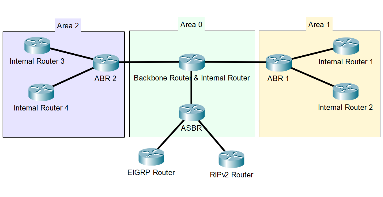
OSPF Hierarchy
OSPF networks are often organized into areas, with one central area known as Area 0, or the Backbone Area. OSPF routing protocol allows for the division (or grouping) of a large Autonomous System into smaller groupings called Areas. Link State Advertisement is limited to one area. For example, LSAs in Area 9 are contained within that area only. All OSPF routers in the same area share the same topological database.
- Autonomous System Border Routers (ASBRs) - ASBRs are routers that connect OSPF domains to external Autonomous System/Routing Process/Routing Domain, such as other OSPF domains or non-OSPF networks (such as RIPv2, EIGRP, BGP).
- Backbone Routers - Internal routers that are in backbone area (area 0). The OSPF hierarchy begins with the backbone area (area 0), which is the central and most critical part of the OSPF domain. All other areas in the OSPF network must be directly connected to the backbone area. The backbone area serves as the core routing infrastructure for OSPF and is responsible for interconnecting different OSPF areas.
- Area Border Routers (ABRs) - Located in between different areas (such as area 0 and area 1). Have interfaces in multiple areas. They play a critical role in OSPF’s hierarchical design by facilitating routing between different OSPF areas by advertising summarized routes to the backbone area, and maintaining separate LSDBs for each area they are connected to.
- Internal Router - Routers that are only in a single area (such as area 1 or area 2). Have no interface in any other area (within a single OSPF area). Internal routers are typically found within non-backbone areas (area 1, area 2, area 3, etc.) in an OSPF network.
Designated Router (DR) & Backup Designated Router (BDR)
In a multi-access network, multiple routers can be connected to the same network segment, such as an Ethernet LAN. OSPF routers on such networks form adjacencies with each other to exchange LSAs and maintain a consistent view of the network topology. Without any mechanism to control this process, every router would attempt to send LSAs to every other router on the network, leading to excessive network traffic and increased processing overhead.
- Designated Router (DR) : To address these challenges, OSPF elects a single DR for each multi-access network segment. This router collects LSAs from all routers on the segment, encapsulates them into a single LSA called a Type 2 LSA (Network LSA), and floods this Network LSA to all routers on the segment. The DR is elected through an OSPF process based on router priorities and Router ID. The router with the highest priority becomes the DR. If priorities are tied, the router with the highest Router ID is elected. The DR minimizes network traffic by acting as a central point for LSA exchange.
- Backup Designated Router (BDRR) : While the DR plays a vital role, it’s important to ensure network redundancy in case the DR fails. This is where the BDR comes in. The BDR is the router with the second-highest priority or, in the absence of priorities, the second-highest Router ID. It is essentially the backup for the DR. The BDR monitors the status of the DR. If the DR becomes unavailable or fails, the BDR can quickly take over as the new DR without requiring a new election process. Having a BDR ensures network stability and prevents a prolonged loss of the DR role, which could disrupt OSPF operations on the segment.
Basic Implementation of OSPF
1) Initialize OSPF routing process and enter the OSPF router configuration mode :
- The process ID value represents a number between 1 and 65,535 and is selected by the network administrator. The process ID value is locally significant.
- It is considered best practice to use the same process ID on all OSPF routers.
Router(config)# router ospf <process-id>
2) Explicitly configure Router-ID for a router :
- Router-ID is in IP address format, which is four decimal numbers separated by dots. For example, 1.1.2.2
Router(config-router)# router-id 1.1.2.2
3) Enable OSPF routing on a specific interface port with an IP network :
- “network” syntax is used to enable OSPF on interfaces. Any interfaces on a router that match this part of the command are enabled to send and receive OSPF packets.
- Wildcard mask is the inverse of a subnet mask. To calculate a wildcard mask, subtract the network subnet mask from the broadcast subnet mask (IP Addressing and Subnetting topic) Wildcard mask.
- The “area <area-id>” syntax refers to the OSPF area.
Router(config-router)# network <network-address> <wildcard-mask> area <area-id>
OR
- We can also configure OSPF directly on the interface. For example, interface Gigabit Ethernet 0/1.
Router(config)# int GigabitEthernet 0/1
Router(config-if)# ip ospf <process-id> area <area-id>
4) Suppress OSPF routing on an interface :
- Passive interfaces prevent the transmission of routing messages through an interface, but still allow that network to be advertised to other routers.
Router(config-router)# passive-interface <interface-id>
5) (Modifying OSPF Cost) Adjust the reference bandwidth :
- Changing the reference bandwidth does not actually affect the bandwidth capacity on the link; rather, it simply affects the calculation used to determine the metric.
- This command must be configured on every router in the OSPF routing domain.
- The reference bandwidth value is expressed in megabits per second (Mbps).
- To return to the default reference bandwidth, use the value of 100.
Router(config-router)# auto-cost reference-bandwidth <value>
6) (Modifying OSPF Cost) Manually set the OSPF cost value :
- Reasons to manually set the cost value include :
- The administrator may want to influence path selection within OSPF, causing different paths to be selected than what normally would be given default costs and cost accumulation.
- Connections to equipment from other vendors who use a different formula to calculate OSPF cost.
Router(config-if)# ip ospf cost <value>
7) Clearing and reloading the OSPF process :
Router# clear ip ospf process
OSPF Tuning (Default Route Propagation)
- What is Default Route Propagation ? : OSPF has the ability to propagate a default route to the routers within the OSPF routing domain. This default route points to a gateway of last resort and helps routers in the network reach destinations outside their own network. This is often done at the edge or border routers, such as ASBRs, which connect the OSPF domain to external networks.
1) The command to propagate a default route :
- This command instructs the router to be the source of the default route information and propagate the default static route in OSPF updates.
Router(config-router)# default-information originate
OSPF Tuning (Modify OSPF Intervals)
- What is Hello and Dead Intervals ? :
- The Hello Interval is a timer that determines how often OSPF routers send Hello packets to their neighbors on a shared network segment. OSPF Hello packets are transmitted to multicast address
224.0.0.5(all OSPF routers) every 10 seconds. This is the default timer value on multiaccess and point-to-point networks. - The Dead Interval is another timer that specifies the maximum amount of time that can elapse without receiving Hello packets from a neighbor before the router considers that neighbor to be unreachable or “dead”. If Hello packets are not received within the Dead Interval, the router assumes the neighbor is no longer operational and removes that neighbor from its LSDB. The router floods the LSDB with information about the down or “dead” neighbor out of all OSPF-enabled interfaces. Cisco uses a default of 4 times the Hello interval. This is 40 seconds on multiaccess and point-to-point networks.
- The Hello Interval is a timer that determines how often OSPF routers send Hello packets to their neighbors on a shared network segment. OSPF Hello packets are transmitted to multicast address
1) The command to manually modify OSPF Hello and Dead intervals :
- To restore the default interval, use the “no” form in this command.
Router(config-router)# ip ospf hello-interval <seconds>
Router(config-router)# ip ospf dead-interval <seconds>
Verify OSPF Configuration
Verifying OSPF configuration is an important step to ensure that the protocol is functioning as intended.
1) Display the necessary information about the routing protocols configured in a router :
Router# show ip protocols
2) Display detailed information about OSPF configurations :
Router# show ip ospf
3) Display information about the specific interface that is enabled into the OSPF process :
Router# show ip ospf interface <interface-id>
4) Briefly display information about OSPF-enabled interfaces :
Router# show ip ospf interface brief
5) Display lists of information about adjacencies that have been formed :
Router# show ip ospf neighbor
6) Display lists of information related to the OSPF database :
Router# show ip ospf database
7) Displays the IP routing table :
Router# show ip route
OR
- specifically the OSPF routing table.
Router# show ip route ospf