Note: This blog post explains the fundamental routing concepts and basic configurations of IPv4 routing. The IPv6 routing configuration will be explained in another blog post IPv6 Routing Configurations (Static & Dynamic Routing). Before diving into the intricacies of routing, it’s important to have a solid understanding of some fundamental networking concepts including : Network Devices, Network Topologies, IP Addressing and Subnetting, OSI Model, Switching, and Cisco Router Initial Configuration. These concepts provide the foundational knowledge that will help you grasp routing topics effectively.
Routing is the process of directing data packets from a source to a destination across a network or series of interconnected networks. In simpler terms, routing can be thought of as finding the best path for data to travel through a network in order to reach its intended destination. Routing involves making decisions based on various factors, such as network topology, link conditions, and routing protocols. A routing table is used to determine the most efficient path to reach the destination. These decisions are typically managed by specialized devices called routers, which examine the destination address of a data packet and determine where to forward it next in order to reach its final destination. A router is a specialized computer that requires the same components to operate as a computer. Routers have specialized ports and network interface cards to interconnect devices with other networks. Routers can have various types of ports, each serving a specific function in network communication and management.
- Ethernet Ports : These ports are used to connect devices within the same local network using Ethernet cables. They provide high-speed data transfer between devices and are labelled as FastEthernet (100 Mbps) or GigabitEthernet (1 Gbps) ports.
- WAN Port : The Wide Area Network (WAN) port is used to connect the router to an external network, such as the internet or a corporate network.
- Serial Ports : Serial ports (such as RS-232 or RS-485) are used for connecting to legacy devices and equipment that use serial communication protocols.
- Auxiliary Port : The auxiliary port is often used for out-of-band management and remote access to the router.
- Console Port : The console port is used for direct local management and configuration of the router via a serial connection.
- RJ-45 Console Port : In addition to the traditional serial console port, Cisco routers may have a modern RJ-45 console port for console management.
- Management Ports : Some routers may have dedicated management ports for remote access and management.
- USB Ports : USB ports on routers serve various purposes, including connecting USB storage devices for file sharing and firmware updates.
- Fiber Ports : Some routers feature fiber-optic ports for connecting to high-speed fiber networks.
- PoE (Power over Ethernet) Ports : Some routers offer PoE ports that provide both data connectivity and electrical power to devices like IP phones, cameras, and access points.
How Does Data Flow in Routers?
The process begins when a device, such as a computer or a server, generates data that needs to be sent to another device over a network. This data is divided into smaller units called data packets. Each data packet is given a source and a destination address. These addresses are typically represented as IP addresses. The source device sends the data packet to its default gateway, which is usually the router that connects the local network to the wider network. The router examines the destination IP address of the data packet. The router consults its routing table, which contains information about various network paths and their associated costs. The routing table helps the router determine the best path for forwarding the data packet towards the destination. Based on the routing table, the router determines the next hop, which is the next router that the data packet should be sent to, using the appropriate outgoing interface (this router is chosen because it is closer to the destination or has a more direct connection). If the destination IP address does not belong to a connected network or is not in the routing table, the packet is sent to the Gateway of Last Resort (default route - more details in Static Routing section). The data packet travels from router to router, hopping through the network, following the path determined by the routing decisions. The destination router delivers the packet to the destination device based on the internal addressing of the local network. If the original data was divided into multiple packets, the destination device reassembled the packets in the correct order to reconstruct the original data.
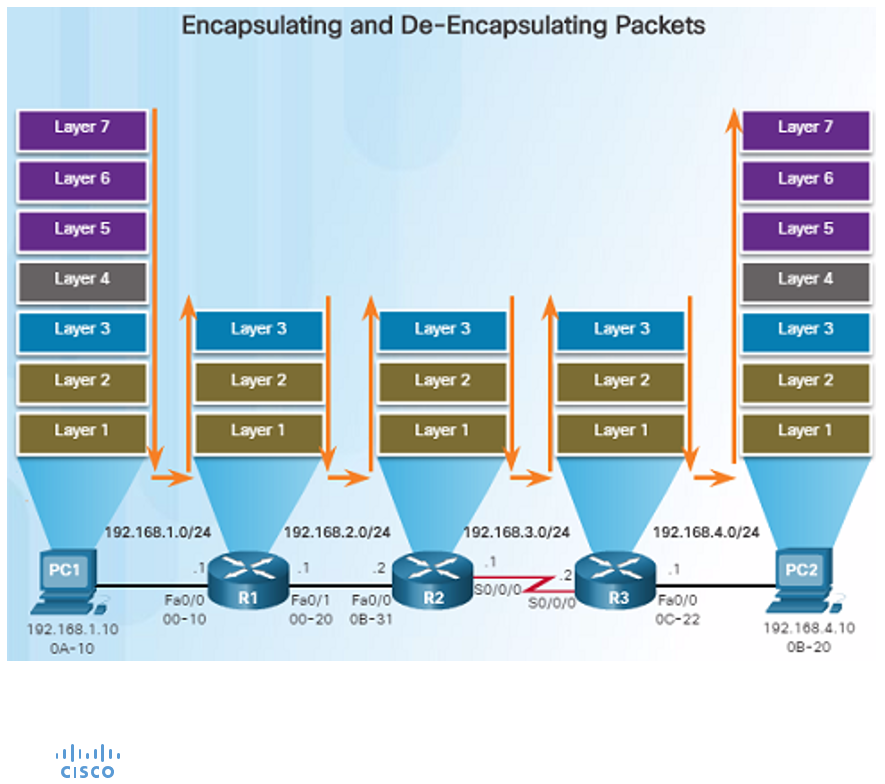
Data flow in routers involves the processes of encapsulating and de-encapsulating packets as they move from one network segment to another.
1. Receiving Data (De-encapsulation)
When a router receives data from one of its interfaces (incoming traffic), it performs the following steps:
- Frame Reception : The router receives an Ethernet frame (Layer 2, Data Link layer) on one of its interfaces (for example, Ethernet port). The frame includes a Layer 2 header that contains the source and destination MAC addresses, along with an FCS (Frame Check Sequence) for error detection.
- FCS Check : The router checks the frame’s FCS to ensure that the data has not been corrupted during transmission. If the FCS is valid, the router proceeds. If not, the frame is discarded.
- De-encapsulation to the IP Layer : The router strips off the Layer 2 header and extracts the packet (Layer 3, Network layer) from within the frame. The packet contains an IP header with source and destination IP addresses.
- Routing Table Lookup : The router examines the destination IP address in the packet and checks its routing table to determine the best next-hop IP address or exit interface to forward the packet toward the final destination. It selects the best path based on routing protocols, static routes, or default routes.
2. Forwarding Data (Encapsulation)
Once the router determines where to send the packet, it encapsulates it in a new Layer 2 frame for transmission out of the appropriate interface:
- Frame Creation : A new Layer 2 frame is constructed with the source and destination MAC addresses of the next-hop device or interface (for example, the router’s interface and the MAC address of the next-hop device, such as another router or the destination host).
- Encapsulation : The original IP packet is placed inside the new frame. The Layer 3 (IP) information is not changed unless Network Address Translation (NAT) or TTL (Time to Live) decrementing is involved.
- FCS Generation : The router computes a new FCS for the frame and appends it to ensure error checking on the next hop.
3. Transmission of the Frame
The router sends the newly encapsulated frame out of the selected interface (for example, Ethernet port, Serial port, etc.) towards the next device in the path (next-hop router or the destination host).
Example of Data Flow:
- Step 1 (De-encapsulation on Router-A) : Router-A receives a frame from a host on its LAN. It checks the frame’s FCS, removes the Layer 2 header, and extracts the IP packet.
- Step 2 (Routing Decision on Router-A) : Router-A looks at the destination IP address and determines that the best path to that IP is through Router-B, which is the next-hop router.
- Step 3 (Encapsulation on Router-A) : Router-A encapsulates the IP packet into a new frame. The frame has the source MAC address of Router-A’s interface and the destination MAC address of Router-B’s interface.
- Step 4 (Transmission to Router-B) : The frame is sent to Router-B. Router-B receives the frame, performs de-encapsulation, looks at the IP packet, and repeats the process until the packet reaches its final destination (either another router or the destination host).
Routed Protocol VS Routing Protocol
Routed protocols and routing protocols are two different concepts in computer networking.
Routed Protocols
A routed protocol is a set of rules and conventions used to format and process data packets for transmission between devices on a network. These protocols define how data is structured, addressed, and encapsulated into packets before being sent across the network. Routed protocols are responsible for determining the logical addressing scheme used to identify devices and their locations within a network. Examples of routed protocols include :
- Internet Protocol (IP) : The most common routed protocol used on the internet and many private networks. It provides unique IP addresses to devices and enables them to communicate across networks.
- IPX (Internetwork Packet Exchange) : Used in Novell NetWare networks.
- AppleTalk : Used in Apple networks.
Routed protocols focus on the format and addressing of data packets (how data is organized and addressed), ensuring that data can be properly routed between devices within a network or across interconnected networks.
Routing Protocols
Routing protocols are a set of rules and algorithms used by routers to determine the optimal path for forwarding data packets from a source to a destination. These protocols allow routers to exchange information about network topology, reachability, and metrics or indicator values (such as link cost or bandwidth) with each other. By sharing this information, routers collectively build and update their routing tables, which contain information about available network paths. Routing protocols all into two main categories :
- Interior Gateway Protocols (IGPs) : These protocols are used to exchange routing information within a single autonomous system (AS) or network. Examples include :
- RIP (Routing Information Protocol)
- OSPF (Open Shortest Path First)
- EIGRP (Enhanced Interior Gateway Routing Protocol)
- Exterior Gateway Protocols (EGPs) : These protocols are used to exchange routing information between different autonomous systems. Examples includes :
- BGP (Border Gateway Protocol) - Most widely used EGP on the internet.
Routing protocols focus on how routers exchange information and make decisions about forwarding data.
Directly Connected Network VS Remote Network
There are two terms in routing concept that we need to understand :
- Directly Connected Network : A directly connected network refers to a network segment that is physically attached to a router’s interface. In other words, it’s a network that can be reached by the router without the need for additional hops through other routers.
- Remote Network : A remote network refers to a network segment that is not directly connected to the router where the routing decision is being made. In other words, a remote network is a destination network that is located beyond the immediate neighbors of the router.
Administrative Distance
Administrative Distance (AD) is a concept used in routing protocols to determine the trustworthiness or preference of a particular route when multiple routing sources provide conflicting routing information for the same destination network. It is a numerical value assigned to each routing source or protocol, indicating its credibility in providing routing information. A lower administrative distance value indicates a higher priority for the corresponding routing source. AD value associated with a particular route can often be seen in the routing table. Examples of AD values :
- 0 : Directly Connected Interface
- 1 : Static Route
- 20 : eBGP (External BGP)
- 90 : EIGRP
- 100 : IGRP
- 110 : OSPF
- 115 : IS-IS
- 120 : RIP
- 200 : iBGP (Internal BGP)
Static Routing
Static routing is a networking configuration in which network administrators manually specify the paths that data packets should take to reach their destinations. In static routing, the routing decisions are predetermined and do not change unless the administrator manually updates the routing table. Static routing is often used in scenarios where network topologies are simple and stable, and where specific routing paths need to be enforced for security or performance reasons.
Configuring Recursive Static Route
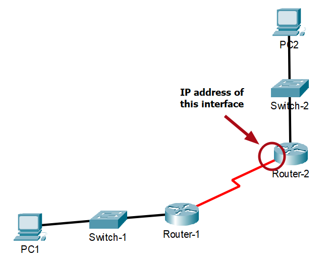
A recursive static route is a type of static route that specifies the next-hop router’s IP address to reach a destination network. Recursive static route is a static route that forwarding packets to the next hop.
For example, we are now configuring Router-1, and the next-hop router is Router-2 :
- network-address : Destination network address of the remote network to be added to the routing table.
- subnet-mask : Subnet mask of the remote network to be added to the routing table.
- ip-address : The next-hop router’s IP address. For example, 172.16.13.1.
Router-1(config)# ip route <network-address> <subnet-mask> <ip-address>
Configuring Directly Attached Static Route
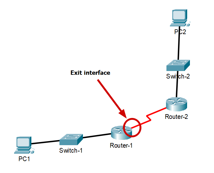
A directly attached static route is a type of static route that specifies the router’s exit interface that is directly connected to the next-hop router. Directly attached static route is a static route that forwarding packets to the exit interface.
For example, we are now configuring Router-1, and the next-hop router is Router-2 :
- network-address : Destination network address of the remote network to be added to the routing table.
- subnet-mask : Subnet mask of the remote network to be added to the routing table.
- exit-interface : The outgoing interface (one of the router’s own interfaces that is directly connected to the next-hop router) to forward packets to the destination network. For example, Serial 0/0/0 or GigabitEthernet 0/1.
Router-1(config)# ip route <network-address> <subnet-mask> <exit-interface>
Fully Specified Static Route
- Both the exit interface and the next-hop router’s IP address are specified.
- When the exit interface is an Ethernet network, a fully specified static route is used.
Router(config)# ip route <network-address> <subnet-mask> <exit-interface> <ip-address>
Configuring Default Static Route
A default static route (or default route) is a special type of static route used to define a path that a router should take when it needs to forward data packets to any destination that is not explicitly listed in its routing table. Instead of dropping the packet or generating on error, the router forwards the packet to the next-hop specified in the default route. In other words, it’s used to direct traffic to a default next-hop router. The default route uses no specific destination network address or destination network subnet mask; instead, it uses a wildcard address (wildcard address and wildcard mask are different concepts - IP Addressing and Subnetting topic). Default static route are commonly used :
- To route traffic from a local network to the internet.
- To route traffic from stub router (a router with only one upstream neighbor router) or stub network (a network that has only one route to reach other networks).
In Cisco IOS (Internetworking Operating System) terminology, the default route is often referred to as the “gateway of last resort”. It’s the route that a router uses when it doesn’t know how to reach a specific destination. A default route ensures that data packets are not dropped when a router doesn’t have a specific route for a destination.
- 0.0.0.0 0.0.0.0 : This is a wildcard address that matches any destination IP address and network address, means “all addresses” or “any destination”. In CIDR notation, it represented as
0.0.0.0/0. - ip-address / exit-interface : A default route can use either a next-hop router’s IP address or an exit interface as its next-hop specification.
Router(config)# ip route 0.0.0.0 0.0.0.0 <ip-address/exit-interface>
Configuring Floating Static Route
A floating static route, also known as a backup static route or a backup route, is a type of static route configuration used to provide redundancy and failover in case the primary route becomes unavailable. It allows a network administrator to specify an alternative path for traffic to take if the primary route fails. The term “floating” refers to the fact that the backup route has a higher administrative distance, making it less preferred than the primary route under normal circumstances. The configuration of the floating static route is the same as the other static route configurations above, with a higher administrative distance :
- Configure the primary route first before setting up a floating static route as a backup.
- network-address : Destination network address of the remote network to be added to the routing table.
- subnet-mask : Subnet mask of the remote network to be added to the routing table.
- ip-address : The next-hop router’s IP address. For example, 172.16.13.1.
- administrative-distance : Consider using a value higher than the default administrative distance for a static route, which is 1. Use a value higher than 1.
Router(config)# ip route <network-address> <subnet-mask> <ip-address> <administrative-distance>
Verify a Static Route
The routing table displays information about the available routes, including their destination networks, next-hop addresses, metrics, and administrative distances.
This command shows the IPv4 routing table :
- “S” indicates static route.
- “S*” indicates default route (“/0” mask indicates none of the bits are required to match - Wildcard Mask in IP Addressing and Subnetting topic).
Router# show ip route
Dynamic Routing
A dynamic routing protocol is a set of rules and algorithms that allow routers within a network to automatically exchange information about network topology, reachability, and other routing-related data. Dynamic routing protocols can scale to accommodate large and complex networks. The purpose of dynamic routing protocols :
- Dynamically discover and adapt to changes in the network (such as link failures, congestion, or new routes).
- Ability to find a new best path if the current path is no longer available.
- Maintaining up-to-date routing information.
Dynamic routing protocols allow routers to discover and learn about the presence of other routers and networks in the same network domain. When network topology changes occur, such as a link failure or the addition of new devices, dynamic routing protocols automatically adjust the routing tables to reflect the changes. Dynamic routing protocols use various metrics or indicator values (such as link cost, bandwidth, delay, etc.) to calculate the best paths for data packets based on real-time network conditions. Dynamic routing protocols continuously exchange updates and information about network changes. There is a term called “Autonomous System” or “AS” in dynamic routing that we need to understand :
- Autonomous System (AS) refers to a set of routers and networks that operate under a single administrative domain and share a consistent routing policy. It represents a logical unit within the global internet. Each Autonomous System is assigned a unique identifier called an Autonomous System number (ASN). ASNs are used to distinguish and identify individual ASes in the routing system. AS numbers are usually 16-bit numbers, ranging from 0 to 65535. In other words, an AS represents a network domain under a single administrative control with a consistent routing policy.
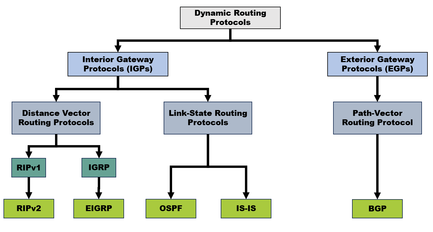
Dynamic routing protocols are categorized into two main groups with different routing algorithms based on the scope of their operation and the area of the network they cover.
Interior Gateway Protocols (IGPs)
Interior Gateway Protocols are routing protocols that operate within a single autonomous system (AS). IGPs are used to exchange routing information and make routing decisions within the boundaries of a single AS. There are two types of routing protocols in IGPs :
1) Distance Vector
Distance Vector routing protocols use the concept of distance (often measured in terms of hop count) to determine the best path to a destination. The fundamental concept underlying Distance Vector routing is based on two key elements, which are “distance” and “vector”. The “distance” in Distance Vector routing protocols represents the metric used to determine the cost or desirability of a route to a destination network. This metric can be hop count, bandwidth, delay, or another measure. A lower distance value usually indicates a better path. The “vector” in Distance Vector routing protocols represents the direction and information needed to forward data to a destination network. This includes the next-hop router or exit interface that should be used to reach the destination. In simpler terms, the “vector” is the set of instructions that indicates where to send data, and the “distance” is the metric (indicator value) that helps routers determine the best route among different options.
Distance Vector routing protocols are often colloquially referred to as “routing by rumours” because of the way they operate, which involves routers sharing information about network paths with their neighboring routers. The term “routing by rumours” highlights certain characteristics of Distance Vector routing protocols :
- Limited Information : Routers only have information about their directly connected networks and the routes learned from their neighboring routers. They don’t possess a complete view of the entire network topology.
- Indirect Exchange : Routers share information through periodic updates sent to their immediate neighbors. These updates contain routing information about known networks and their associated metrics.
- Iterative Process : The routing updates are exchanged iteratively, and routers gradually learn about more distant networks as updates propagate through the network. Routers don’t have a global perspective of the network; they rely on information passed along by their neighbors.
- Convergence Over Time : Just as rumours can take time to spread through a social network, it takes time for routing information to propagate across the network and for routers to converge to a consistent view of the network topology. Converge is the process by which routers adjust their routing tables to reflect network changes. Slow convergence can lead to temporary routing inconsistencies.
- Count-to-Infinity Problem : Distance Vector routing protocols can suffer from the count-to-infinity problem, where a router wrongly assumes that a distant network is reachable through a neighboring router. This can lead to routing loops and inaccurate routing information.
- Inaccuracies and Delays : Just as rumours can be inaccurate or altered as they are passed along, Distance Vector routing information can be affected by inaccuracies and delays due to network conditions.
Other key characteristics of Distance Vector routing protocols :
- Neighbor-to-Neighbor Communication : Routers in Distance Vector routing protocols communicate directly with their immediate neighbors. They share information about their routing table entries and learn about routes from other routers’ updates.
- Loop Prevention Techniques : To prevent routing loops, Distance Vector routing protocols use techniques such as Split Horizon and Route Poisoning. These mechanisms restrict the advertisement of routes to avoid sending them back to the router from which they were learned.
- Simple Configuration : Distance Vector routing protocols often have simpler configurations compared to Link-State routing protocols.
- Less Network Overhead : Distance Vector routing protocols generally have lower network overhead compared to Link-State routing protocols because they only exchange updates about their own routes rather than full topology information.
Distance Vector routing protocol as an analogy, similar to a destination sign board. If we want to go to Kuala Lumpur from Pahang and we don’t have a map, we must rely on the destination sign board. If the sign board tells us that Kuala Lumpur is in the West direction and 100 km away (<- Kuala Lumpur 100 km), then we need to go in the West direction to go to Kuala Lumpur. Similar to Distance vector routing protocols, it doesn’t have a full view of the path to get to a destination network. In other words, it doesn’t have a complete “road map” of the network; it is only aware of what its neighbor has told it (routing by rumour).
Examples of Distance Vector routing protocols include :
- RIP(Routing Information Protocol) : RIP is a classic example of a distance-vector protocol. It uses hop count as the metric and employs a maximum hop count limit to prevent routing loops. RIPv2 introduces subnet support and some improvements over the original RIP. It’s suitable for small to medium-sized networks.
- IGRP (Interior Gateway Routing Protocol) : IGRP is a Cisco-proprietary distance-vector which means it is implemented only by Cisco routers. It’s less commonly used today in favor of newer protocols. IGRP has been superseded by EIGRP (Enhanced Interior Gateway Routing Protocol),which is also a Cisco proprietary protocol.
- EIGRP (Enhanced Interior Gateway Routing Protocol) : EIGRP is sometimes referred to as a hybrid routing protocol because it has characteristics of distance vector and some of those of link-state protocols. However, the fundamental operation of EIGRP is based on the principles of a distance-vector protocol. EIGRP (Enhanced Interior Gateway Routing Protocol)
2) Link-State
Link-State routing protocols focus on exchanging information about the state of network links and using this information to build a detailed and accurate map of the network’s topology. This map is then used to calculate the shortest paths to destination networks. Link-State routing protocols offer a more sophisticated and efficient approach to routing compared to Distance Vector routing protocols. Key characteristics of Link-State routing protocols include :
- Topology Information Exchange : Routers in a Link-State routing protocol periodically exchange information about the state of their directly connected links. This information is typically referred to as Link-State Advertisements (LSAs).
- Detailed Network View : Each router collects LSAs from its neighbors to build a comprehensive picture of the entire network’s topology. This view includes information about routers, links, their states (UP or DOWN), and associated metrics (costs).
- Link-State Database (LSDB) : Routers maintain a Link-State Database containing the collected LSAs from all routers in the network. The LSDB provides an up-to-date representation of the network’s topology.
- Shortest Path Calculation : Using the information from the LSDB, routers calculate the shortest paths to all other routers in the network. This is often achieved using algorithms such as Dijkstra’s algorithm, which ensures optimal routing paths based on link costs.
- Efficiency and Scalability : Link-State routing protocols converge more quickly than Distance Vector routing protocols and are generally more efficient in large networks. They make routing decisions based on the most accurate and current network information.
- Triggered Updates : Unlike Distance Vector routing protocols that use periodic updates, Link-State protocols typically use triggered updates. These updates are sent only when there are changes in the network’s topology, such as link failures or recoveries.
- Hierarchical Routing : Many Link-State routing protocols support hierarchical routing by dividing networks into areas. Each area maintains its own LSDB, reducing the complexity of LSDB management in large networks.
- Loop Prevention : Link-State routing protocols inherently prevent routing loops due to their flooding mechanism. Routers do not forward LSAs back to the router from which they received them.
Link : Router interface
State : Description of an interface and its relationship to neighboring routers
Link-state protocols have a full view of the path to get to a destination network. In other words, it has a complete “road map” of the network or area.
Examples of Link-State routing protocols include :
- OSPF (Open Shortest Path First) : OSPF is a well-known link-state protocol that uses a cost metric (often based on bandwidth) to calculate the shortest path. OSPF is suitable in multivendor environments. OSPF (Open Shortest Path First)
- IS-IS (Intermediate System to Intermediate System) : IS-IS is similar to OSPF but is often used in service provider environments. It uses a link-state database and a metric known as “metric-style”, which is used to calculate the best path.
Exterior Gateway Protocols (EGPs)
Exterior Gateway Protocols are routing protocols that operate between different autonomous systems (ASes). They are used to exchange information and make routing decisions between separate administrative domains. EGPs are generally associated with the use of the Path Vector routing algorithm.
1) Path Vector
Path Vector routing protocols are a type of routing protocol that builds on the concepts of both Distance Vector and Path Vector approaches. Path Vector routing protocols aim to provide more control and flexibility in network routing, particularly in large-scale environments. Path Vector routing protocols share some similarities with both Distance Vector and Path Vector routing protocols, but they have distinct characteristics :
- Path Information Exchange : Similar to Distance Vector, Path Vector routing protocols exchange routing information with their neighbors. However, instead of just sharing distance metrics, they exchange more comprehensive path information.
- Path Vector Data Structure : Path Vector routing protocols maintain a routing table that includes information about the path to reach a destination network, not just the distance. This path information can include a list of autonomous systems that the route traverses.
- Autonomous System Path : The “Path Vector” aspect comes from the inclusion of information about the sequence of ASes that a route has traversed. This helps in preventing routing loops, as each AS adds its own identifier to the path.
- Path Attributes : In BGP, routes are associated with various attributes that provided additional information about the route, including AS path, next-hop router, origin, and other attributes used to influence routing decisions.
- Path Selection : Path Vector routing protocols often provide more sophisticated path selection mechanisms compared to simple Distance Vector routing protocols.
- Policy-Based Routing : Path Vector routing protocols such as BGP are well-suited for policy-based routing, where network administrators can control and influence the selection of paths based on specific criteria.
- Slow Convergence : Path Vector routing protocols tend to have slower convergence compared to Link-State routing protocols. This is particularly evident in the internet’s BGP routing, where routes can take time to propagate and stabilize due to the global nature of the network.
Path Vector routing protocols offer more advanced and flexible routing capabilities compared to simple Distance Vector routing protocols. They provide control over routing paths and policies, making them suitable for complex network environments where different autonomous systems need to interact and communicate routing information.
- BGP (Border Gateway Protocol) : BGP is the most well-known path vector protocol used on the internet for interdomain routing. BGP exchanges path vectors (routes) between autonomous systems and supports complex routing policies.
Administrative Distance versus Mask Length in Dynamic Routing
Administrative Distance is only used to determine the best route when there are two or more routes with the same destination network subnets. If the destination network subnets are different, both routes will be added to the routing table. Refer to this explanation video (Udemy course) and other references on the internet : Administrative Distance VS Mask Length - The Complete Networking Fundamentals Course(Udemy)
References
- Internet Protocol
- Chapter 1: Routing Concepts - Cisco NetAcad Powerpoint Presentation Slide
- Chapter 2: Static Routing - Cisco NetAcad Powerpoint Presentation Slide
- Chapter 3: Dynamic Routing(Basic Concept) - Cisco NetAcad Powerpoint Presentation Slide
- Module 5: Dynamic Routing - Cisco NetAcad Powerpoint Presentation Slide
- Udemy - The Complete Networking Fundamentals Course
- Static routing
- Configuring Static Routing - Cisco Docs
- Cisco Networking Academy’s Introduction to Routing Dynamically (Refer to the Contents - Complete chapter of Dynamic Routing)
- Understanding Dynamic and Static Routing
- What is the difference between Routing Protocols and Routed Protocols
- Routing and routed protocols
- What is an autonomous system? What are ASNs?
- Autonomous system (Internet)
- Distance Vector Routing Protocols - Cisco Docs
- Link State Routing Protocols - Cisco Docs
- Link State Routing Protocols - The Complete Networking Fundamentals Course(Udemy)
- Administrative Distance VS Mask Length Link State Routing Protocols - The Complete Networking Fundamentals Course(Udemy)
- Dijkstra’s algorithm
- Shortest Path First (SPF)
- Administrative distance
- Routing Overview - Cisco Docs
- Dijkstra’s algorithm
- Shortest Path First (SPF)
- Administrative distance